# Non- zero R output from lock-in with no input
**URL:** https://forum.liquidinstruments.com/t/non-zero-r-output-from-lock-in-with-no-input/1008
**Category:** Moku:Go
**Created:** [July 29, 2024, 7:35pm UTC](https://forum.liquidinstruments.com/t/non-zero-r-output-from-lock-in-with-no-input/1008 "2024-07-29T19:35:14Z")
**Posts on this page:** 9
**Page:** 1
### Author:  [@John](https://forum.liquidinstruments.com/u/John)
#### Post date: [July 29, 2024, 7:35pm UTC](https://forum.liquidinstruments.com/t/non-zero-r-output-from-lock-in-with-no-input/1008/1 "2024-07-29T19:35:14Z")
I’m setting up a Moku:Go lock-in to measure an optical detector output. The laser input to the detector is mechanically chopped at ~5.2 kHz to modulate it.
The detector signal is ~2 mVp-p, and AC coupled into Input 1. There is a 50 ohm terminator on Input 1, as required by the detector.
The signal into Input 2 is the sync signal from the optical chopper, a clean ~2.2 Vp-p square wave, 50% duty cycle, ~5.2 kHz.
I set the gain to +72.6 dB to get about +4.5 volts DC at Output 1. When I blind the detector, I still get about +2.3 volts out. The leakage current from the detector is blocked by AC coupling, so why don’t I see ~0 volts?
I’m not sure what the operating environment limits are for the Go, but the ambient temperature in the room is about 90F, 55% RH.
Setup:
% Saved 2024-07-25 T 10:08:23 -0700
Moku:Go Lock-In Amplifier
Input 1, AC coupling, 0 dB attenuation
Input 2, AC coupling, 0 dB attenuation
External PLL demodulation: AC coupling, 1 MOhm impedance, 0 dB attenuation, phase 180.000 000 deg
Lowpass filter corner frequency 15.9 Hz (time constant 9.99 ms), slope 6 dB / octave
Output 1 - R signal, +72.6 dB gain, invert off, offset 0.000 0 V, output enabled
Output 2 - Theta signal, +0.0 dB gain, invert off, offset -150.0 mV, output enabled
Thanks!
---
### Author:  [@indira](https://forum.liquidinstruments.com/u/indira)
#### Post date: [July 30, 2024, 2:40am UTC](https://forum.liquidinstruments.com/t/non-zero-r-output-from-lock-in-with-no-input/1008/2 "2024-07-30T02:40:24Z")
Hi John,
Are you able to share the screenshots of the 2.3 V with me so I can help you understand what is happening here?
Thanks,
Indira
---
### Author:  [@John](https://forum.liquidinstruments.com/u/John)
#### Post date: [July 30, 2024, 9:50pm UTC](https://forum.liquidinstruments.com/t/non-zero-r-output-from-lock-in-with-no-input/1008/3 "2024-07-30T21:50:35Z")
See below for descriptions of files.
(Attachment Detector not blocked.zip is missing)
---
### Author:  [@indira](https://forum.liquidinstruments.com/u/indira)
#### Post date: [July 31, 2024, 2:30am UTC](https://forum.liquidinstruments.com/t/non-zero-r-output-from-lock-in-with-no-input/1008/4 "2024-07-31T02:30:05Z")
Hey John, it looks like your images aren’t loading properly, so I’ll just tell you what I am thinking could be happening.
You mentioned that the signal is 2 mVpp, so the amplitude will be 1 mV. After the amplification, I would expect the output voltage to be around 4.265 V, which sounds like what you are seeing before blocking the detector.
The 2.3 V you’re seeing when the detector is blind sounds in the region of expected to me, given that the gain is very large and that the noise power within the demodulation frequency range is amplified. This can cause the non-zero output you are seeing. So, if the 2.3 V signal you are seeing behaves like noise then I think that is okay.
If the 2.3 V is not behaving like noise, then can you try upload your screenshots again?
Cheers,
Indira
---
### Author:  [@John](https://forum.liquidinstruments.com/u/John)
#### Post date: [August 6, 2024, 11:06pm UTC](https://forum.liquidinstruments.com/t/non-zero-r-output-from-lock-in-with-no-input/1008/7 "2024-08-06T23:06:16Z")
Resending because my text did not hit the previously unknown 20 character minimum.
Input 2 to Lock-in

---
### Author:  [@John](https://forum.liquidinstruments.com/u/John)
#### Post date: [August 12, 2024, 11:05pm UTC](https://forum.liquidinstruments.com/t/non-zero-r-output-from-lock-in-with-no-input/1008/8 "2024-08-12T23:05:16Z")
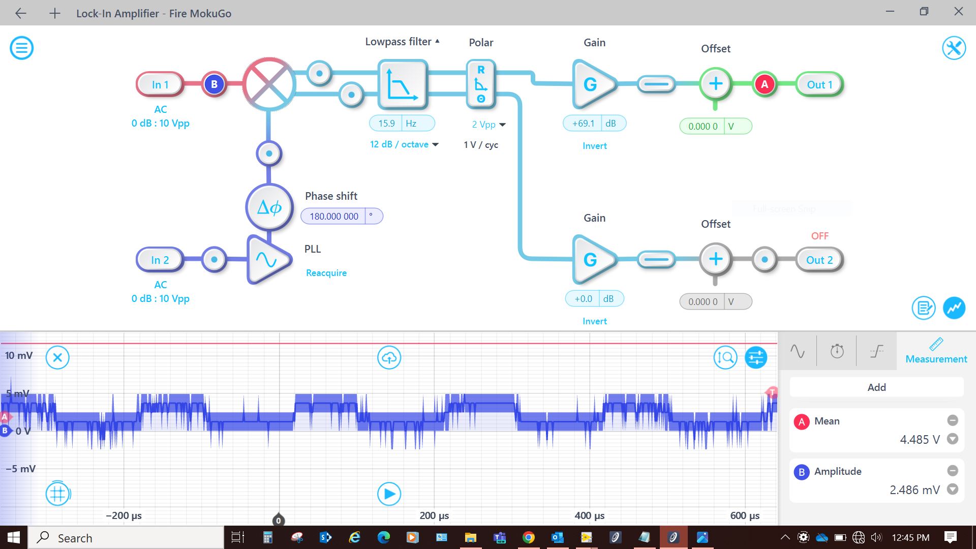
Sorry, I thought the other two attachments went through. Here’s the screenshot showing Input 1 and Output 1.
---
### Author:  [@John](https://forum.liquidinstruments.com/u/John)
#### Post date: [August 12, 2024, 11:07pm UTC](https://forum.liquidinstruments.com/t/non-zero-r-output-from-lock-in-with-no-input/1008/9 "2024-08-12T23:07:09Z")
This screenshot shows the input and output signals with the detector blocked.

---
### Author:  [@indira](https://forum.liquidinstruments.com/u/indira)
#### Post date: [August 13, 2024, 6:33am UTC](https://forum.liquidinstruments.com/t/non-zero-r-output-from-lock-in-with-no-input/1008/10 "2024-08-13T06:33:50Z")
Hi John,
I’ve been recreating this on my end and I have a couple of suggestions for you.
Firstly, I would suggest that you change your Polar range setting from 2 Vpp to 7.5 mVpp, as the two Input signals multiply together to produce a 4.8 mVpp signal through the LP filter, so the 7.5 mVpp range is more appropriate.
Secondly, what are your PLL settings? When I set the PLL bandwidth to 10 Hz I get a signal with less visible quantization, with a lower signal mean in the tens of uV (with a gain of 0 dB). I’d love to know if you get similar results when you have these settings and remove the gain from your system, as that will give me an understanding of the underlying signal without the gain.
The only other thing I came across in my testing was some potential crosstalk between the cables, as after I moved the cables around, the LIA Output 1 mean value had reduced. So, if you have the chopper signal and the photodiode signal running next to each other for any distance, then even blocking the detector might still be getting some signal at the target frequency due to crosstalk. You can check if this is affecting your measurement by disconnecting the signal cable at the Moku and observing any changes, rather than just blocking the detector.
Let me know how you go,
Indira
---
### Author:  [@John](https://forum.liquidinstruments.com/u/John)
#### Post date: [August 14, 2024, 5:03am UTC](https://forum.liquidinstruments.com/t/non-zero-r-output-from-lock-in-with-no-input/1008/11 "2024-08-14T05:03:03Z")
Hi Indira,
Summarizing the setup - the purpose of this setup is to measure a low signal coming from an optical detector. The beam impinging on the detector is a CW laser beam chopped at about 5 kHz with an optical chopper. The chopper also provides a synchronous square wave output of about 4.7 Vpp. I’m looking at the magnitude, R, at Out 1 which will be proportional to In 1. Since the two inputs are the same frequency, I should be able to adjust the phase shift for a difference of zero degrees, producing a DC only signal at Out 1 and zero out of Theta. With that in mind, I’m setting a minimum cutoff frequency and the steepest roll off (24 dB / octave). Am I thinking correctly?
Addressing your questions:
_Firstly, I would suggest that you change your Polar range setting from 2 Vpp to 7.5 mVpp, as the two Input signals multiply together to produce a 4.8 mVpp signal through the LP filter, so the 7.5 mVpp range is more appropriate._
I understand that the magnitudes of the input signals multiply, but where did you get 4.8 mV? Should I probe the two mixer inputs to see the levels? Selecting the Polar range setting to accommodate the product of the signal magnitudes makes sense and answers a question I had about that setting.
Questions concerning the PLL: